
The Network Layer: Pratical Overview
Let’s dive into a network layer now:
Index
| # | Topic | Short Description |
|---|---|---|
| 1 | Role of the network layer | Host-to-host delivery; runs in every router and host. Forwarding = one router, routing = whole path |
| 2 | Service models | Internet IP = best effort, connectionless datagrams; ATM-style virtual circuits reserve state per call |
| 3 | Inside a router | Input ports → switching fabric → output ports; queues can form at both ends |
| 4 | IPv4 datagram | 20-byte header: TTL, protocol, src/dst; fragments reassembled only at the destination |
| 5 | Addressing | Subnet = shared prefix; CIDR a.b.c.d/x; routers use longest-prefix match |
| 6 | DHCP | Discover → Offer → Request → ACK; also hands out mask, gateway, DNS |
| 7 | NAT | Many private addresses behind one public IP, tracked by port in a translation table |
| 8 | Routing algorithms | Link state = Dijkstra, global view; distance vector = Bellman-Ford, neighbors only |
| 9 | Hierarchical routing | Routers grouped into autonomous systems: intra-AS vs inter-AS |
| 10 | Routing protocols | RIP (DV), OSPF (LS, areas), BGP (path vector, policy) |
| 11 | Broadcast / multicast | Flooding → spanning tree; multicast = only the hosts in a group |
The core role of the network layer
The network layer moves packets host to host across many networks. The sender encapsulates each transport segment into an IP datagram; every router on the way reads the header and passes it on; the receiver hands the segment up to transport. Unlike the application and transport layers, which run only in hosts, the network layer runs in every host and every router.
The network layer has two key functions Forwarding and Routing:
| Forwarding | Routing | |
|---|---|---|
| What | Move a packet from a router’s input port to the right output port | Work out the whole path from source to destination |
| Scope | One router, local | Network-wide |
| Speed | Nanoseconds per packet, in hardware | Seconds, in software |
| Plane | Data plane | Control plane |
| Trip analogy | Getting through one highway interchange | Planning the trip from start to finish |
How do they interact with each other?
The routing algorithm computes the forwarding table; when a packet arrives, the input port looks up its destination address in that table to choose the output link. The control plane can live in two places: the traditional way is a routing algorithm running in every router, talking to its peers; the modern SDN (software-defined networking) way is a remote controller computing tables and installing them into the routers.
Service models
A network could promise delivery, timing or bandwidth just like paying extra for tracked, guaranteed-by-noon courier delivery. The Internet’s IP promises none of it: best effort. Reliability is added above it by TCP (Ch.3).
Service models compared
| Architecture | Service model | Bandwidth guarantee | No loss | In order | Timing | Congestion feedback |
|---|---|---|---|---|---|---|
| Internet (IP) | Best effort | None | No | No | No | No (inferred from loss) |
| ATM | CBR (constant bit rate) | Constant rate | Yes | Yes | Yes | Not needed |
| ATM | ABR (available bit rate) | Guaranteed minimum | No | Yes | No | Yes |
*ATM also offers VBR (variable bit rate) for bursty traffic.
Connectionless vs connection-oriented at the network layer
| Datagram network (Internet IP) | Virtual-circuit network (ATM, X.25, Frame Relay) | |
|---|---|---|
| Setup before sending | None | Call setup reserves a path, like dialing a phone |
| State in routers | None per connection — only the forwarding table | Every router on the path keeps per-call state and resources |
| Forwarding decision | Destination address, looked up per packet | VC number carried in the packet |
| Route changes | Packets of one flow may take different paths | All packets follow the reserved path |
| Where the complexity sits | “Smart” end systems, simple core | “Dumb” end systems (phones), complex core |
| Cost | Cheap, elastic, works over any link type | Expensive to build and run, but can guarantee service |
| Typical use | The Internet | Telecom and banking backbones historically |
Forwarding table size: a table can’t list all ~4 billion IPv4 addresses, so it stores address ranges (prefixes) and matches the destination against them (section 5).
Inside a router
A router basically is a routing processor (control plane) plus a switching machine (data plane): packets enter through input ports, cross a switching fabric, and leave through output ports. The goal is to process packets at line speed; when that fails, queues form and packets get dropped.
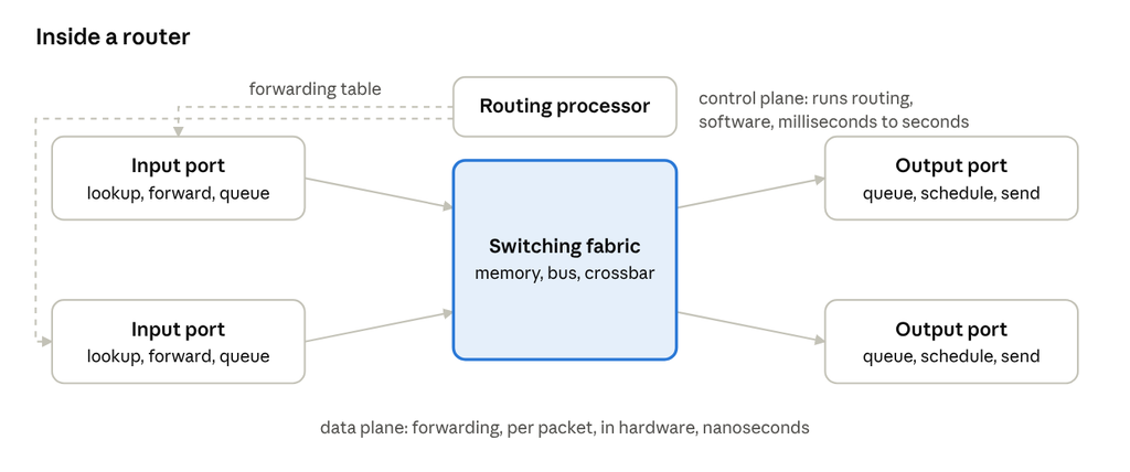
The routing processor computes the forwarding table and copies it to each input port; each packet is then forwarded without involving the processor.
Input ports
- Terminate the physical line, run the link-layer protocol, then look up the destination address in the local copy of the forwarding table (longest-prefix match, often in TCAM hardware).
- Input queuing happens when the fabric can’t take packets as fast as they arrive.
- Head-of-line (HOL) blocking: the packet at the front of an input queue waits for a busy output port, and every packet behind it waits too, even packets heading to idle outputs.
Switching fabric: three generations:
| Type | How it works | Limit |
|---|---|---|
| Via memory | The CPU copies each packet into memory, then to the output (first routers were ordinary computers) | Two memory accesses per packet → memory bandwidth |
| Via bus | Input port writes the packet onto a shared bus, labelled for its output | One packet at a time → bus speed |
| Via crossbar / interconnection network | Many input-output pairs connected in parallel | Only conflicts for the same output |
A fabric running N× faster than the input lines eliminates input queuing.
Output ports
- Buffer packets when the fabric delivers faster than the outgoing link can send: this is where most loss happens.
- Scheduling decides the next packet to send: FIFO, priority, round robin, weighted fair queuing (the basis of QoS / net-neutrality debates).
- Drop policy when full: drop-tail or active queue management (RED, CoDel). Too much buffering causes huge delays: bufferbloat.
The IPv4 datagram and fragmentation
The Internet’s network layer has three parts: IP (addressing, datagram format, handling conventions), routing protocols (path selection) and ICMP (error reporting and signalling: ping, traceroute, “destination unreachable”).
IPv4 header: 20 bytes without options (drawn 32 bits wide)
 0       4       8               16    19                31  (bits)
+-------+-------+---------------+-----+-------------------+
|version|  IHL  |  DSCP / ECN   |      total length        |
+-------+-------+---------------+-----+-------------------+
|        identification          |flags|  fragment offset  |
+---------------+---------------+-----+-------------------+
|      TTL      |   protocol    |      header checksum     |
+---------------+---------------+-------------------------+
|                source IP address (32 bits)               |
+---------------------------------------------------------+
|              destination IP address (32 bits)            |
+---------------------------------------------------------+
|         options, if any (e.g. timestamp, record route)   |
+---------------------------------------------------------+
|        data: TCP or UDP segment, ICMP message ...        |
+---------------------------------------------------------+| Field | Purpose |
|---|---|
| Version, IHL | IPv4; header length in 32-bit words |
| DSCP / ECN (old “type of service”) | Priority class; congestion marking |
| Total length | Header + data, in bytes (max 65,535) |
| Identification, flags, fragment offset | Fragmentation and reassembly |
| TTL (time to live) | Decremented by each router; at 0 the packet is dropped and an ICMP “time exceeded” is sent back — prevents endless loops |
| Protocol | Which transport gets the payload: 6 = TCP, 17 = UDP, 1 = ICMP |
| Header checksum | Covers the header only; recomputed at every hop because TTL changes |
| Source / destination address | 32 bits each |
Overhead: 20 bytes TCP + 20 bytes IP = 40 bytes per segment, plus the application’s own headers.
Fragmentation and reassembly
- Every link has an MTU (maximum transmission unit), e.g. 1,500 bytes on Ethernet. A datagram larger than the next link’s MTU is split into fragments.
- All fragments keep the same identification; the fragment offset says where the fragment’s data sits in the original, in units of 8 bytes; the MF (more fragments) flag is 1 on every fragment except the last. A DF (don’t fragment) flag forbids splitting.
- Reassembly happens only at the final destination, never in routers.
Worked example: a 4,000-byte datagram (20-byte header + 3,980 bytes of data) meets a link with MTU 1,500
| Fragment | Total length | Data bytes | Offset (×8 bytes) | MF flag |
|---|---|---|---|---|
| 1 | 1,500 | 1,480 (bytes 0–1,479) | 0 | 1 |
| 2 | 1,500 | 1,480 (bytes 1,480–2,959) | 185 | 1 |
| 3 | 1,040 | 1,020 (bytes 2,960–3,979) | 370 | 0 |
Check: 1,480 + 1,480 + 1,020 = 3,980; 1,480 / 8 = 185.
IPv4 addressing: subnets, CIDR, allocation, longest-prefix match
An IP address identifies an interface, not a device. The high-order bits are the network (subnet) part, the rest the host part. Devices on the same subnet reach each other directly; traffic between subnets must go through a router.
Interfaces:
- A router has several interfaces, each with its own IP address.
- A host usually has one or two (e.g. wired Ethernet and Wi-Fi), each with its own address.
- IPv4 addresses are 32 bits, written as four decimal octets:
192.168.1.17.
Subnets:
- A subnet is a set of interfaces sharing the same high-order bits that can reach each other without a router (a home Wi-Fi where every device starts
192.168.1.x). - Counting recipe: detach every interface from its router or host; each island left is one subnet.
- Example: 6 subnets: 3 host LANs + 3 router-to-router links.
CIDR Classless InterDomain Routing: address written as a.b.c.d/x, where x = number of network bits (the prefix). Replaced the old fixed class A/B/C system so prefixes can be any length. The table below shows some examples:
| Prefix | Mask | Addresses | Usable hosts | Typical use |
|---|---|---|---|---|
| /30 | 255.255.255.252 | 4 | 2 | Point-to-point router link |
| /24 | 255.255.255.0 | 256 | 254 | Home or small-office LAN |
| /23 | 255.255.254.0 | 512 | 510 | ~400 hosts (big venue Wi-Fi) |
| /22 | 255.255.252.0 | 1,024 | 1,022 | Campus building |
| /16 | 255.255.0.0 | 65,536 | 65,534 | Large organization |
Formula: addresses = 2^(32 − x); usable hosts = 2^(32 − x) − 2, because the all-zeros host part names the network and the all-ones host part is the subnet’s broadcast address.
Worked example: ~400 hosts: a /24 (254 hosts) is too small, so take a /23: 23 network bits, 9 host bits → 2^9 = 512 addresses → 510 usable. For 200.23.16.0/23: range 200.23.16.0–200.23.17.255, hosts .16.1–.17.254, broadcast 200.23.17.255.
Who hands out addresses?
- ICANN / IANA manages the global pool and delegates large blocks to the five regional internet registries: ARIN, RIPE NCC, APNIC, LACNIC, AFRINIC.
- RIRs allocate blocks to ISPs (and large organizations).
- ISPs split their block and assign sub-blocks to customers — your home router’s public IP comes from here.
Route aggregation (summarization) an ISP holding 200.23.16.0/20 gives eight organizations a /23 each (200.23.16.0/23, 200.23.18.0/23, … 200.23.30.0/23) but advertises only the single /20 to the rest of the Internet: “send me anything whose first 20 bits match”. This keeps global routing tables small.
Longest-prefix match: when several table entries match a destination, the router uses the most specific (longest) one.
| Prefix in table | Output link |
|---|---|
200.23.16.0/21 (third octet 16–23) | 0 |
200.23.24.0/24 (third octet 24 only) | 1 |
200.23.24.0/21 (third octet 24–31) | 2 |
default 0.0.0.0/0 | 3 |
200.23.22.161 → link 0. 200.23.24.170 matches both /24 and /21 → longest wins → link 1. 200.23.30.5 → link 2. 8.8.8.8 → default, link 3. This is also why an organization can move to a new ISP: the new ISP advertises the more specific /23 and it beats the old ISP’s /20.
| Range | Meaning |
|---|---|
10.0.0.0/8, 172.16.0.0/12, 192.168.0.0/16 | Private (RFC 1918): not routed on the Internet |
127.0.0.0/8 | Loopback |
169.254.0.0/16 | Link-local (no DHCP answer); 169.254.169.254 = cloud metadata service |
100.64.0.0/10 | Carrier-grade NAT shared space |
224.0.0.0/4 | Multicast |
255.255.255.255 | Limited broadcast, never forwarded by routers |
DHCP: how a host gets an address
A host can be hard-coded with an address (you type IP, mask, gateway and DNS into its settings, which means knowing the network first), or get everything automatically from DHCP (Dynamic Host Configuration Protocol) basically “plug and play”, and what every modern device does by default.
More details
- For home network the DHCP server is the home Wi-Fi router, or a dedicated server in an enterprise. A subnet without its own server uses a DHCP relay agent in the router to forward requests to a central server.
- Runs over UDP: server port 67, client port 68.
- The address is leased for a limited time and renewed while in use, so addresses are reused when devices leave.
- Besides the IP address, DHCP returns the subnet mask, the default gateway (first-hop router — the way off the subnet) and DNS server addresses.
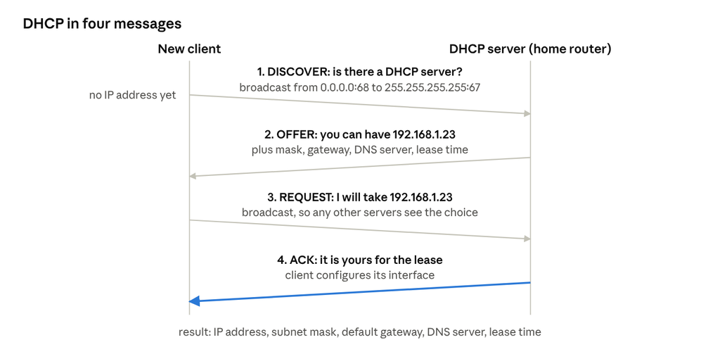
The client has no address yet, so it broadcasts; the server offers an address, the client asks for it, and the server confirms (the “DORA” sequence). If a lease is still valid, only steps 3–4 are needed.
NAT: Network Address Translation
There aren’t enough IPv4 addresses for every device, so a whole home or office uses private addresses inside (RFC 1918: 10.0.0.0/8, 172.16.0.0/12, 192.168.0.0/16, never routed on the Internet) and shares one public address outside. The NAT router rewrites addresses and ports and remembers each mapping in a translation table.
How it works:
- Laptop 10.0.0.1 sends a request from port 3345 to 128.119.40.186:80 (a web server).
- The NAT router replaces the source with its public address and a new port, 138.76.29.7:5001, and records the pair in its table.
- The server replies to 138.76.29.7:5001: it never sees the private address.
- The router looks up port 5001, rewrites the destination back to 10.0.0.1:3345, and delivers it on the LAN.
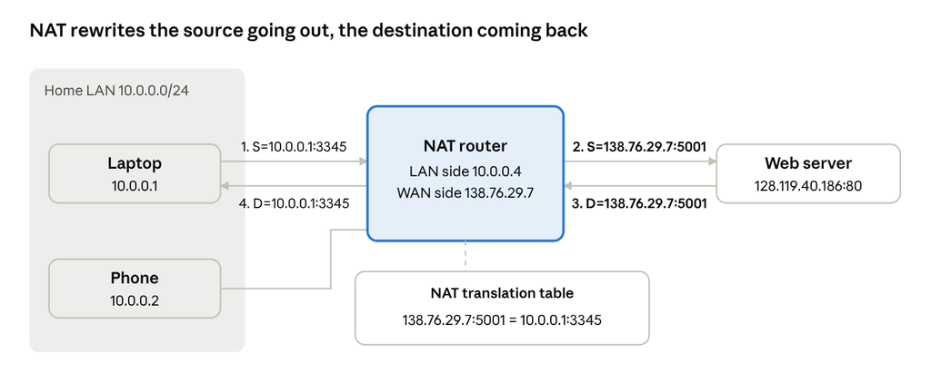
The port number is what lets one public address carry thousands of simultaneous connections from different inside hosts.
Pros:
- One public IP (from the ISP) for any number of devices.
- Change inside addresses without telling the outside world; change ISPs without renumbering the home network.
- Inside devices aren’t directly reachable from outside: unsolicited inbound packets have no table entry and are dropped. That’s a side effect, not a firewall.
Cons:
- Routers should only work up to layer 3, but NAT rewrites transport-layer ports.
- Breaks the end-to-end principle: hosting a server or peer-to-peer app behind NAT needs port forwarding, UPnP or NAT traversal (STUN / TURN / ICE, hole punching).
- The real fix for address shortage is IPv6 (128-bit addresses). ISPs short of IPv4 now even NAT their customers (carrier-grade NAT, 100.64.0.0/10).
Routing algorithms: link state vs distance vector
The model the network as a graph: routers are nodes, links are edges, and each edge has a cost (set by the operator, often from bandwidth, delay or distance). A routing algorithm finds the least-cost path between routers; the result fills the forwarding tables.
Classification
| Axis | Option A | Option B |
|---|---|---|
| Information | Global: every router knows the full topology and all link costs → link-state (LS) | Decentralized: a router knows only its neighbors and link costs to them, and learns the rest iteratively → distance-vector (DV) |
| Change over time | Static: routes set by hand, change rarely | Dynamic: routes recomputed as links fail or costs change |
Small networks often use static routes (simple, configured by hand); larger networks use dynamic protocols, either LS or DV.
Link state: Dijkstra’s algorithm
- Every router floods its link costs to all others (link-state broadcast), so all have the same map.
- Each runs Dijkstra: grow a set N’ of nodes whose least-cost path is known, one node per step, always adding the closest remaining node, then update neighbors’ distances.
- Complexity O(n²) for n nodes (O(n log n) with a heap).
Worked example: (standard textbook graph; the transcript’s walkthrough is garbled). Link costs: u–v 2, u–x 1, u–w 5, v–x 2, v–w 3, x–w 3, x–y 1, w–y 1, w–z 5, y–z 2.
| Step | N’ (settled) | D(v), p(v) | D(w), p(w) | D(x), p(x) | D(y), p(y) | D(z), p(z) |
|---|---|---|---|---|---|---|
| 0 | u | 2, u | 5, u | 1, u | ∞ | ∞ |
| 1 | u x | 2, u | 4, x | 2, x | ∞ | |
| 2 | u x y | 2, u | 3, y | 4, y | ||
| 3 | u x y v | 3, y | 4, y | |||
| 4 | u x y v w | 4, y | ||||
| 5 | u x y v w z |
D = current least cost from u, p = previous node on that path. Bold = node settled at the next step (ties broken arbitrarily).
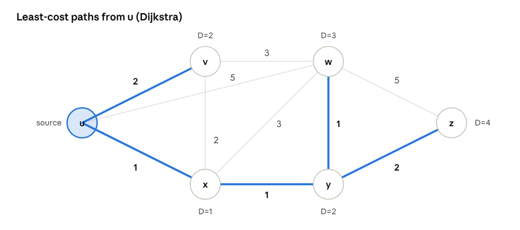
Result: u’s forwarding table: to v use link (u,v); to x, y, w, z use link (u,x). Least-cost path to z: u → x → y → z, cost 4.
Distance vector: Bellman-Ford
- Each router keeps a distance vector: its estimated cost to every destination.
- Bellman-Ford equation: d_x(y) = min over neighbors v { c(x,v) + d_v(y) } cost to y is the best of (cost to a neighbor + that neighbor’s cost to y).
- From time to time, and whenever its vector changes, a router sends it to its neighbors only; they recompute and pass changes on. Iterative, asynchronous, distributed.
- Good news travels fast, bad news travels slow: after a link cost increase or failure, two routers can keep pointing at each other and raise their costs step by step the count-to-infinity problem. Mitigations: poisoned reverse (advertise infinity back to the neighbor you route through), and a small “infinity” (RIP uses 16).
| Link state (OSPF) | Distance vector (RIP) | |
|---|---|---|
| Knowledge | Full topology | Neighbors’ vectors only |
| Messages | Every router floods to all: O(n·E) | Only between neighbors |
| Convergence | Fast: one O(n²) computation | Varies; can loop, count to infinity |
| Robustness | A bad router advertises a wrong link cost; others still compute their own tables | A bad router advertises a wrong path cost, and the error spreads through the whole network |
Hierarchical routing autonomous systems
The algorithms in the above section assume one flat network where every router is equal. That fails on the real Internet for two reasons: scale (hundreds of millions of destinations can’t all sit in every forwarding table, and LS flooding would swamp the links) and administrative autonomy (each network owner wants to run and hide its own network). The fix: group routers into autonomous systems (ASes).
More details:
- An AS is a group of routers under one administration (an ISP, a university, a large company) identified by an AS number.
- All routers inside an AS run the same intra-AS routing protocol (RIP or OSPF) and know about each other, but not about routers in other ASes.
- Gateway (border) routers sit at the edge of an AS and also run the inter-AS protocol (BGP) with gateway routers of neighboring ASes.
- A router’s forwarding table is filled by both: intra-AS routing for destinations inside, inter-AS + intra-AS routing for destinations outside.
- Grouping also follows function and geography: most traffic stays local, so keeping it inside one AS is efficient.
What a router does with an outside destination
- Destination inside my AS → forward along the intra-AS path.
- Destination outside → the AS must learn, via inter-AS routing, which destinations are reachable through which neighboring AS, and spread that knowledge to all its routers.
- The router then picks the gateway to use and installs “destination prefix → interface toward that gateway” in its forwarding table.
- If several gateways can reach the destination, a common choice is hot-potato routing: hand the packet to the gateway with the lowest intra-AS cost, i.e. get it out of my network as cheaply as possible.
Internet routing protocols: RIP, OSPF, BGP
Inside an AS (intra-AS, also called interior gateway protocols) the common choices are RIP (distance vector), OSPF (link state) and Cisco’s EIGRP; between ASes (inter-AS) there is exactly one: BGP, the protocol that “glues the Internet together”.
RIP: Routing Information Protocol
- 1980s, shipped with BSD Unix when ordinary computers acted as routers. Still found on small networks, rare elsewhere.
- Distance vector; the metric is hop count, with a maximum of 15 (16 = unreachable). The hop count is kept in routing tables, not carried in packets (packets carry TTL)
- Neighbors exchange full distance vectors every 30 s over UDP port 520 (up to 25 destination subnets per advertisement).
- No advertisement from a neighbor for 180 s → neighbor or link declared dead, routes through it invalidated, new advertisements sent; uses poisoned reverse against loops.
OSPF: Open Shortest Path First
- Open = publicly specified, so routers from different vendors interoperate. Not “open” as in the first path.
- Link state: each router floods link-state advertisements (one entry per neighbor) to all routers in its area, then runs Dijkstra locally. Advertisements are resent on any change and periodically. Runs directly over IP (protocol 89).
- Improvements over RIP: message authentication (only trusted routers can inject routes), multiple equal-cost paths used in parallel (ECMP), per-link costs for different traffic types, integrated multicast support, and hierarchy.
- Two-level hierarchy: the AS is split into areas plus a backbone (area 0). LSAs flood only within an area. Area border routers summarize their area’s networks into the backbone; backbone routers run OSPF within the backbone; AS boundary routers connect to other ASes.
BGP: Border Gateway Protocol
- The inter-AS protocol of the whole Internet; a path-vector protocol running over TCP port 179.
- eBGP: learn which prefixes are reachable through each neighboring AS. iBGP: spread those reachability facts to all routers inside the AS.
- A BGP route = prefix + attributes: AS-PATH (list of ASes the advertisement passed through — also used to reject loops) and NEXT-HOP (the gateway to use).
- Route selection, in order: local preference (policy), shortest AS-PATH, closest NEXT-HOP (hot potato), then tie-breakers.
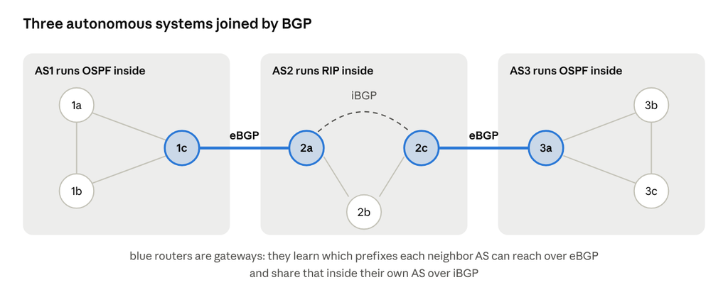
Gateways 1c, 2a, 2c and 3a speak eBGP across AS borders; inside AS2, 2a and 2c share what they learned over an iBGP session while RIP handles the internal paths.
BGP policy: what makes BGP different from RIP/OSPF: the operator decides which routes to accept and which to advertise, based on business relationships, not just cost. Classic example: a customer network connected to two providers does not advertise a route from provider A to provider B, so it never carries transit traffic between them for free. (Per-application choices such as “send video one way, email another” are policy-based routing and QoS inside a network: not something BGP decides.)
Why separate intra- and inter-AS protocols?
| Intra-AS | Inter-AS | |
|---|---|---|
| Policy | Single administration, none needed | Admins control who carries whose traffic |
| Scale | Hierarchy (OSPF areas) keeps tables small | Only aggregated prefixes cross AS borders |
| Goal | Performance: least-cost paths | Policy first, performance second |
Broadcast and multicast routing
Unicast means one sender to one receiver; broadcast – one sender to all nodes; multicast – one sender to a group of interested receivers.
Broadcast: ways to reach every router
| Method | How | Problem |
|---|---|---|
| N-way unicast | Source sends a separate copy to each destination | Wasteful; the source must know every destination |
| Uncontrolled flooding | Every router forwards a copy out of every other link | Cycles create a broadcast storm of endless copies |
| Controlled flooding | Each router forwards a packet only once: remember (source, sequence number) pairs, or forward only if it arrived on the shortest path back to the source (reverse-path forwarding) | Still some redundant copies |
| Spanning tree | Build a tree that touches every router exactly once and forward only along it | Tree must be built and maintained |
In practice, routers do not forward IP broadcasts between subnets: 255.255.255.255 (used by DHCP DISCOVER) stays on the local subnet, and directed broadcasts to remote subnets are disabled by default.
Multicast
- A multicast address (
224.0.0.0/4) names a group; hosts join and leave with IGMP, talking to their local router. - Routers build delivery trees between themselves with multicast routing protocols such as PIM: a tree per source (source-based) or one shared tree per group (rooted at a core / rendezvous point).
- Where some routers don’t support multicast, multicast routers are joined by tunnels through ordinary routers: logically adjacent, physically several hops apart (the 1990s MBone worked this way).
- Uses: IPTV and video classes inside a campus or ISP, software distribution, financial market data feeds. Multicast is rarely routed across the public Internet.
That was a tough one. Let’s meet again at Link Layer 🙂